other
  • NTC thermistor guide: B value, resistance curve and selection
    October 26, 2026 NTC thermistor guide: B value, resistance curve and selection
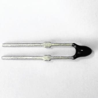
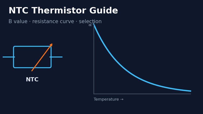
    An NTC thermistor is a temperature sensor whose resistance falls as it heats up. NTC stands for negative temperature coefficient. It is made from sintered metal-oxide ceramic, and it is described by two numbers: R25, the resistance at 25 °C, and a B value that sets how steeply the resistance falls. The second of those numbers causes more field problems than any other parameter in thermistor work, because the same physical device can honestly be labelled 3950 or 3988 depending on which two temperatures it was measured between. This guide covers what that means for your calibration, and what to specify so it does not bite you. Published 3 September 2026. Reviewed by the Focusens technical department. Where the resistance curve comes from Thermistor behaviour is not fixed by a single international curve the way platinum RTDs are. Where a PT100 is interchangeable because IEC 60751 defines one relationship for every compliant part, an NTC follows the curve of its own ceramic formulation. The generic requirements, terminology and test methods for these devices sit in IEC 60539-1:2022, edition 4.0, published 15 December 2022, covering directly heated negative temperature coefficient thermistors made from transition metal oxide materials. That difference is the root of everything below. Two thermistors can both be honestly described as “10 kΩ NTC” and follow measurably different curves. The usual working model is the Beta equation: R(T) = R₂₅ · exp[ B · (1/T − 1/298.15) ] with T in kelvin and B in kelvin. Rearranged for temperature: T = 1 / [ 1/298.15 + ln(R/R₂₅) / B ] The table below is that equation evaluated for a 10 kΩ part with B = 3988 K. It is a model output, not a measured datasheet, and the gap between the two is the subject of the next two sections. Temperature Resistance Temperature Resistance −40 °C 416.4 kΩ 50 °C 3,553 Ω −20 °C 107.8 kΩ 60 °C 2,453 Ω 0 °C 34.02 kΩ 70 °C 1,731 Ω 10 °C 20.31 kΩ 80 °C 1,245 Ω 25 °C 10,000 Ω 100 °C 680 Ω 30 °C 8,020 Ω 125 °C 348 Ω 40 °C 5,269 Ω 150 °C 192 Ω Calculated from the Beta equation above, R25 = 10 kΩ, B = 3988 K. Use a manufacturer's own curve data for design work. Why the same part carries different B values B is not a property you can read off a device. It is a number computed from two resistance measurements at two temperatures: B(T₁/T₂) = ln(R₁/R₂) / (1/T₁ − 1/T₂) Change either temperature and the answer changes, because a real thermistor curve is not a perfect exponential. That is why a datasheet B value always carries a subscript naming the pair it was taken between. In the Focusens catalogue alone, parts are specified against five different reference pairs. Reference pair Meaning Example catalogue entries B25/50 measured between 25 °C and 50 °C 2.19 kΩ B25/50:3470, 50 kΩ B25/50:3950, 1...
    View More
  • PT100 resistance table: full chart (-200 to 850 °C) per IEC 60751
    October 15, 2026 PT100 resistance table: full chart (-200 to 850 °C) per IEC 60751
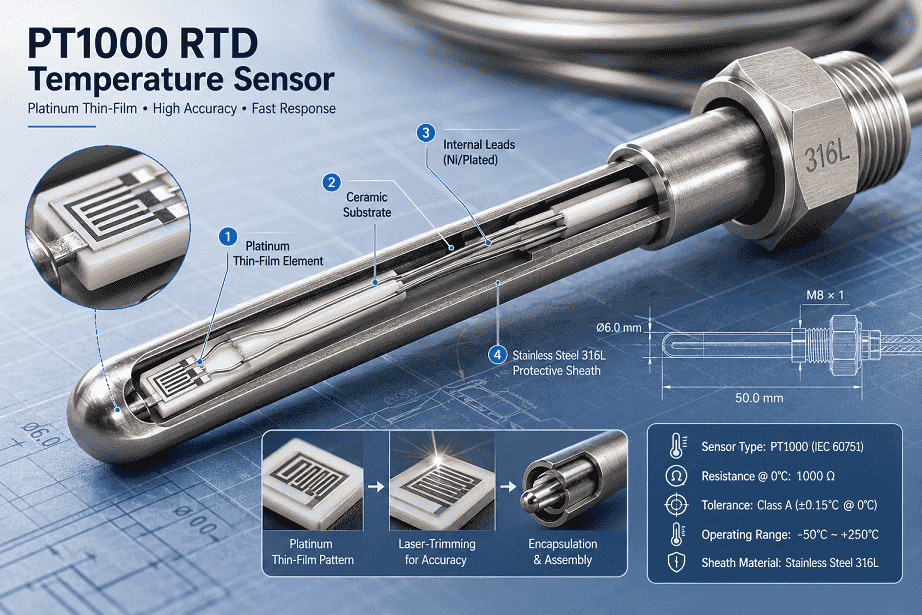
    PT100 Resistance Table: Full Chart -200 to 850 °C (IEC 60751) A PT100 reads 100.00 Ω at 0 °C and 138.51 Ω at 100 °C on the IEC 60751 curve, an average of 0.385 Ω per °C over that span (0.391 Ω/°C right at 0 °C). At room temperature (25 °C) it reads 109.73 Ω. At 100 °C, IEC 60751 allows a Class A sensor ±0.35 °C (±0.133 Ω) and a Class B sensor ±0.80 °C (±0.303 Ω). The tables below give every 1 °C from -200 to 850 °C, read by row and column, plus a °F table. Use the converter for fractional values, or download the full CSV. Updated 15 October 2026: completed the table to every 1 °C up to 850 °C, added a °F table, corrected the slope column and the legacy-curve error figures. Reviewed by the Focusens Engineering Team. What the numbers mean A PT100 is a platinum resistance temperature detector with nominal resistance R0 = 100.00 Ω at 0 °C. Its temperature coefficient α = (R100 - R0) / (100 °C × R0) is 0.00385 °C⁻¹. IEC 60751 writes it as 3.851 × 10⁻³ °C⁻¹, and the equation coefficients give 0.00385055. The same chart on the 1000 Ω base is the PT1000 resistance table. Every PT100 follows the same normalized platinum curve as a PT1000, scaled by a factor of 10. Reference point PT100 PT1000 Local slope, PT100 -200 °C (lower limit) 18.52 Ω 185.20 Ω 0.432 Ω/°C 0 °C (ice point) 100.00 Ω 1000.00 Ω 0.391 Ω/°C 25 °C (room) 109.73 Ω 1097.35 Ω 0.388 Ω/°C 100 °C (steam point) 138.51 Ω 1385.06 Ω 0.379 Ω/°C 200 °C 175.86 Ω 1758.56 Ω 0.368 Ω/°C 850 °C (upper limit) 390.48 Ω 3904.81 Ω 0.293 Ω/°C Datasheets mix two slope figures. 0.385 Ω/°C is the average from 0 to 100 °C, which is how α = 0.00385 is defined. 0.391 Ω/°C is the slope at 0 °C, and it falls to 0.293 Ω/°C at 850 °C. To turn a small resistance error into degrees, such as cable resistance, divide by the local slope: 1 Ω of loop resistance is 2.56 °C at 0 °C and 2.64 °C at 100 °C. The slope of a PT100 falls from 0.432 Ω/°C at -200 °C to 0.293 Ω/°C at 850 °C. The dashed line is the 0 to 100 °C average that α describes. Complete PT100 resistance table The tables cover every 1 °C across the standardized range from -200 to 850 °C, rounded to 0.01 Ω. Read the row for the tens and the column for the units: row 120, column 6 is 126 °C, which reads 148.33 Ω. In the negative table, row -120, column -6 is -126 °C. Negative range, -200 to -1 °C °C 0 -1 -2 -3 -4 -5 -6 -7 -8 -9 -200 18.52 -190 22.83 22.40 21.97 21.54 21.11 20.68 20.25 19.82 19.38 18.95 -180 27.10 26.67 26.24 25.82 25.39 24.97 24.54 24.11 23.68 23.25 -170 31.34 30.91 30.49 30.07 29.64 29.22 28.80 28.37 27.95 27.52 -160 35.54 35.12 34.70 34.28 33.86 33.44 33.02 32.60 32.18 31.76 -150 39.72 39.31 38.89 38.47 38.05 37.64 37.22 36.80 36.38 35.96 -140 43.88 43.46 43.05 42.63 42.22 41.80 41.39 40.97 40.56 40.14 -130 48.00 47.59 47.18 46.77 46.36 45.94 45.53 45.12 44.70 44.29 -120 52.11 51.70 51.29 50.88 50.47 50.06 49.65 49.24 48.83 48.42 -110 56.19 55.79 55.38 54.97 54.56 54.15 53.75 53.34 52.93 52.52 -100 60.26 59.85 59.44 59.04 58.63 58.23 57.82 57.41 57.01...
    View More
  • Thermistor Assembly: 5 Interfaces That Decide Survival
    July 31, 2026 Thermistor Assembly: 5 Interfaces That Decide Survival
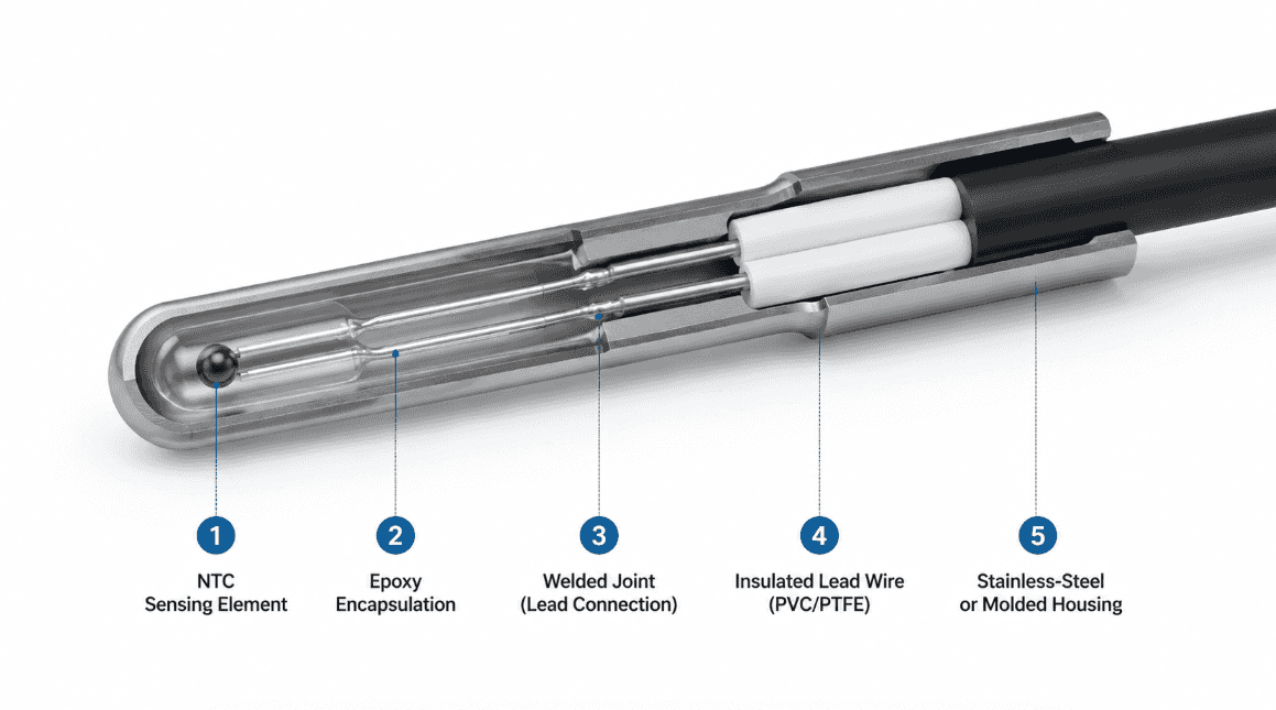
    Direct answerA thermistor assembly is five parts in series — element, encapsulation, lead wire, joint, housing — and each has its own temperature limit, its own failure mode and its own acceptance method. The usable limit of the assembly is the lowest of the five. It is almost never the element. Specify against the weakest interface, and verify the joint by asking about the test, because it is the only one of the five that does not appear on a datasheet. A buyer asks for a 10 kΩ NTC probe rated to 150 °C. What arrives is an assembly in which the bead is comfortable at 150 °C, the epoxy is at its published edge, the PVC-jacketed lead is well past its rating, and the crimp is the part that will actually open. Four of those five regions are on a datasheet somewhere. One is not. What each interface governs The five interfaces do not trade off against each other — each one governs a property the others cannot compensate for. Interface Governs Dominant failure mode How it is verified Element R25, B constant, tolerance band, curve shape Slow resistance drift under long hot or humid service; rarely sudden R–T table or Steinhart–Hart coefficients, plus a stated tolerance and the band it applies over Encapsulation Moisture barrier, upper temperature, thermal mass Water reaching the ceramic–electrode interface; cracking at material boundaries under cycling Damp-heat and temperature-change exposure — the conditions matter more than the pass/fail Lead wire Temperature limit, flex life, chemical and abrasion resistance Insulation softening, cracking, or abrading through where the cable crosses an edge UL style number and the manufacturer's certificate for that style Joint Mechanical and electrical continuity between fine element leads and the extension conductor Intermittent open under vibration or thermal cycling Destructive pull test on a sample basis — see below Housing Thermal coupling to the process, ingress protection, mechanical protection Slow or damped response; seal failure at the cable entry Material and mounting interface on a drawing; ingress by test report with its conditions The joint is the one you have to ask about The joint is where a fine element lead — frequently a different metal from the extension conductor — meets the cable. Welded, soldered, crimped and ultrasonically bonded joints all work in production and all fail differently. A joint that passes a bench continuity check can still open intermittently after a few thousand thermal cycles, and an intermittent open in a control loop presents as a sensor fault long before anyone suspects a mechanical one. There is an industry framework for this, and buyers can quote it directly. IPC/WHMA-A-620, Requirements and Acceptance for Cable and Wire Harness Assemblies, sets out three acceptance classes and, in its Chapter 19, defines pull-force testing, crimp-height measurement and crimp-force monitoring. It also sets inspection conditions that are easy to check on a factory visit: magnification i...
    View More
  • The Cold Chain Behind the Stadium Beer Line
    July 25, 2026 The Cold Chain Behind the Stadium Beer Line
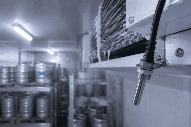
    Direct answerA cold chain is a sequence of custody handoffs, and temperature sensing exists at each one to prove the product never left its band. The chain fails where custody changes — not in the middle of a well-instrumented cold store. A stadium sells beer at 3 °C to seventy thousand people across four hours. Getting there means a chain of refrigerated steps stretching back weeks, each one owned by a different party, each handoff a place where responsibility — and temperature — can be dropped. The engineering lesson generalises well beyond drinks. Every cold chain fails the same way: not in the middle of a monitored space, but at the moments when the product moves between owners and nobody is measuring. Six handoffs, six sensing problems Custody steps and what each one needs from a sensor Step What must be known Sensing approach Why Production / conditioning Process temperature, tightly held Immersion probe, platinum or precision NTC Control point; accuracy is the product spec Cold store Space temperature, many points Multi-drop digital (1-Wire) Twenty points, one data line — wiring is the cost driver, not accuracy Loading dock Exposure time and peak Logger / portable probe The classic failure point — nobody owns the pallet on the dock Transport Continuous record over hours Logger, battery-driven Evidence, not control; low power is the constraint Venue cellar Space and coil temperature NTC probe + defrost sensing Control and defrost termination Dispense line Line temperature at delivery Pipe-clamp NTC Non-invasive on a wetted line; you cannot break into a product line Notice the pattern. Accuracy dominates at the ends — where the product is made and where it is delivered. In the middle, topology and evidence dominate. That distinction should drive the component choice, and it usually doesn't. The cold store: why 1-Wire wins here A cold store needs many points and modest accuracy. That is precisely the DS18B20's case. From the Focusensing FST DS18B20 datasheet: 9–12 bit user-selectable resolution, ±0.5 °C from −10 to +85 °C, 1-Wire open-drain interface, 12-bit conversion in 750 ms maximum, supply 3.0–5.5 V. (Focusens FST DS18B20 datasheet.) The number that matters is not the ±0.5 °C. It is the word open-drain. Many addressable sensors share one data line — twenty probes, one pin, one cable run. Where the wiring is the expensive part and ±0.5 °C sits comfortably inside the product's tolerance band, that topology is worth more than accuracy you would never act on. 5 mm tubular DS18B20 probe — space temperature Waterproof tubular DS18B20 probe — washdown areas Thread-mount DS18B20 probe — where it must not move Flange-mount DS18B20 · all digital assemblies Choosing between a digital probe and a plain thermistor for a pack of points? DS18B20 vs NTC thermistors works the comparison through in detail. The evaporator and the defrost problem A refrigeration evaporator ices up. Ice insulates, capacity falls, the system works harder to do less. So it def...
    View More
  • Pipe-Strap vs Clamp-On Sensor: The Buyer's Call
    July 22, 2026 Pipe-Strap vs Clamp-On Sensor: The Buyer's Call
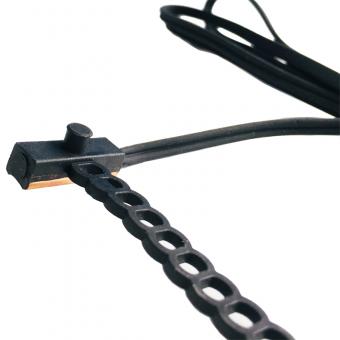
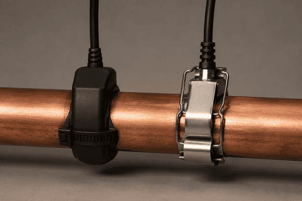
    Direct answerUse a strap-mount sensor when pipe diameter varies across the job and you want one part number to fit all of it. Use a spring clamp when a technician will remove and refit the sensor repeatedly. Use a threaded probe when the reading must be the fluid, not the pipe. "Pipe-strap" and "clamp-on" get used interchangeably in catalogues, which is unhelpful, because the difference is mechanical and it decides how the sensor fails. Both press a sensing element against a pipe from outside. What differs is what supplies the force — and force, contact area and repeatability are the whole game in surface sensing. The three mounting families Mounting method, and what each one is actually good at Strap-mount Spring clamp Threaded / immersion Force source Tensioned strap, ratchet-locked Pre-formed spring steel Thread + seal Pipe size range Wide — one part covers a range Narrow — sized per diameter Fixed fitting Refit by hand Possible; tension is operator-dependent Designed for it Needs draining Contact repeatability Depends on who fitted it High — the spring sets the force Not applicable Measures Pipe surface Pipe surface The medium Break into the pipe? No No Yes The buyer's question is rarely "which is better". It is "which one is still reading correctly in three years" — and there the answers diverge sharply. Three failure modes nobody puts on a datasheet 1 · Tension decay A strap is only as good as the force still in it. Thermal cycling and vibration walk a smooth strap loose. This is exactly why the TPE strap on the Focusensing pipe-clamp carries locking holes on a 4.5 mm pitch — ratchet geometry that holds tension once seated instead of relying on friction. (Pipe-strap product documentation.) If you are evaluating a smooth-band competitor, that is the question to ask. 2 · The air gap you paid to avoid Specify a copper-capped tip for its thermal path, then mount it over a weld seam or a burr, and you have bought a copper cap and installed an air gap. Contact is not binary. A copper tip held 0.3 mm off the pipe performs like a polymer tip and costs more. The general practice here is covered properly in Thermistor Mounting 101 — best practices for accurate temperature measurement. If you fit sensors, read that one before this one. 3 · Wrong-diameter creep A strap sized for 35 mm on a 12 mm line contacts the pipe on a tangent — a line, not a patch. It reads, it just reads slowly and toward ambient. Spring clamps fail the opposite way: right diameter, perfect contact, wrong part on the next pipe size, so the store carries five SKUs. The size question, with real numbers The integrated TPE strap is 110 ± 10 mm long and 7.0 ± 0.2 mm wide, covering pipe outer diameters up to about 35 mm. Past that, a buckle-on extension strap extends the range — that is the extension-chain version. Probe nose length is 6.0 ± 0.5 mm. (Pipe-strap product documentation.) This is where strap-mount wins commercially, and it has nothing to do with physics: one part number co...
    View More
  • How Pipe-Clamp Sensors Keep a 35°C Stadium Cool
    July 17, 2026 How Pipe-Clamp Sensors Keep a 35°C Stadium Cool
    Direct answerA pipe-clamp (clamp-on) temperature sensor measures pipe surface temperature without cutting into the line. In stadium cooling it sits on chilled-water and refrigerant pipes, feeding the controllers that hold safe indoor temperatures when it is 35 °C outside. Seventy thousand people in an enclosed bowl on a 35 °C afternoon is a cooling problem measured in megawatts. The equipment that solves it — chillers, pumps, air handlers, kilometres of insulated pipe — is photographed constantly and understood rarely. The component that decides whether any of it works is none of those things. It is a black plastic lozenge strapped to a pipe in a plant room, and it costs less than the bolts holding the chiller down. Pull that sensor off its pipe and the chiller controlling the loop goes blind. A blind chiller is not a stopped chiller — that would at least be obvious. It is a chiller that keeps running against a number that is wrong, burning money quietly for the length of the tournament. This article walks the cooling chain from plant room to seat, and shows where clamp-on sensing decides the outcome. The number that makes sensor accuracy a budget line Start with a figure most fans never hear. Chiller efficiency moves by roughly 2 percent for every 1 °F of change in chilled-water supply temperature. FacilitiesNet puts it at approximately 2 percent per degree of supply-temperature increase; Quest Design Group gives the same rule of thumb and notes paybacks under a year on larger plants. Georgia Power, quoted by BuildingIQ, is more conservative — about 1 percent per °F above 42 °F in centrifugal machines — with other sources landing between 1.5 and 2 percent. (FacilitiesNet; Quest Design Group; BuildingIQ citing Georgia Power.) Call it 1–2 percent per degree and the conclusion holds either way. A pipe sensor reading 2 °F low tells the chiller to over-cool by 2 °F. At 1–2% per degree that is roughly 2–5% added to compressor energy — every hour, for the whole event. The cheapest part in the loop sets the ceiling on the most expensive one's efficiency. This is not a rounding error dressed up as a story. It is the reason instrumentation appears in the standards at all. ASHRAE's Guideline 22, which defines how to instrument a central chilled-water plant, makes the same argument in standards language: the quality and installation of temperature instrumentation bounds how accurately plant efficiency can be known or controlled. (ASHRAE Guideline 22, Instrumentation for Monitoring Central Chilled-Water Plant Efficiency.) You cannot optimise what you cannot measure, and you cannot measure better than your sensor and its mounting allow. Walking the cooling chain The chiller The chiller makes cold water, typically 6–7 °C (42–45 °F). It controls itself against two measurements above all others: water leaving, water returning. Those two normally use platinum RTDs — PT100 or PT1000 — because platinum drifts little and reads almost linearly against a defined curve...
    View More
  • The Cold Chain Behind the Stadium Beer Line
    July 03, 2026 The Cold Chain Behind the Stadium Beer Line
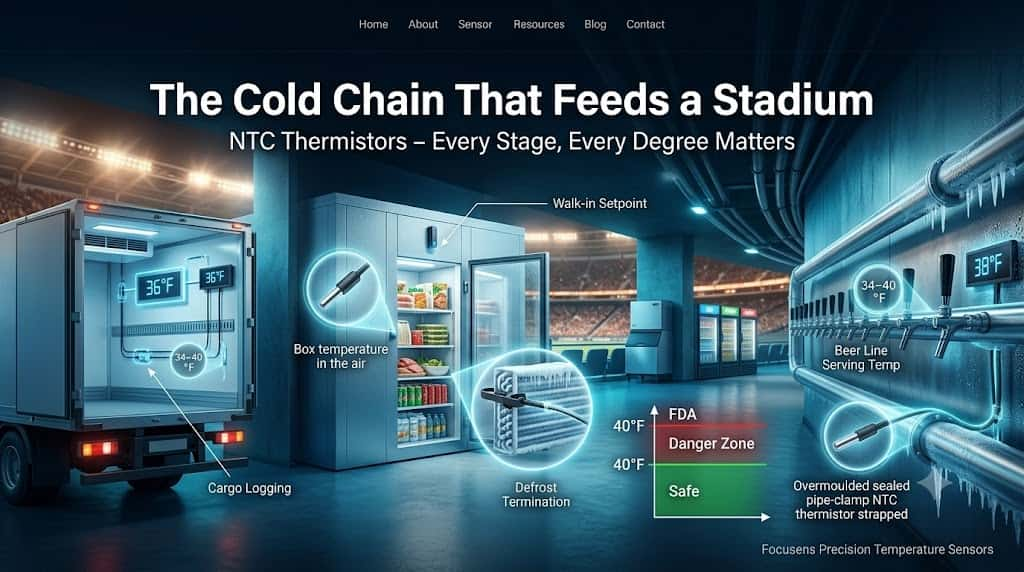
    Direct answerThe cold chain feeding a stadium runs on NTC thermistors at every stage — refrigerated trucks, walk-in coolers, ice machines and chilled beverage lines. They hold food below 40°F (4°C) and drinks at serving temperature, and trigger defrost and alarms when readings drift. A sold-out stadium is a catering operation the size of a small town, and almost everything it serves has to stay cold from the moment it leaves a warehouse. Break the chain anywhere — a reefer that warms in traffic, a walk-in whose coil iced over, a beer line that lost its chill on the last twenty feet to the tap — and the failure shows up in a warm drink or, worse, a sick fan. The thing holding the chain together is unglamorous: a network of NTC thermistors. The line that turns temperature into a legal requirement Food safety runs on a hard number. The US FDA Food Code treats roughly 40°F to 140°F (4°C–60°C) as the "danger zone" where bacteria multiply fastest, so perishable food must be held below 40°F. (US FDA Food Code.) That single threshold is why refrigeration isn't comfort engineering here — it's compliance, logged and audited, and the log comes from sensors. Stage by stage Cold-chain stages, target temperatures, and the sensing at each. Stage Target Sensing role Sensor Refrigerated truck 34–40°F Coil + cargo control, logging Sealed NTC Walk-in cooler 34–40°F Setpoint + defrost termination NTC ×2 roles Walk-in freezer 0°F / −18°C Setpoint + defrost NTC Ice machine ~32°F / 0°C Harvest/cycle NTC, accuracy near 0°C Beverage line 36–41°F Serving-temp check Pipe-clamp NTC The two-sensor trap in every walk-in A walk-in cooler needs two NTC sensors doing different jobs, and confusing them is a classic field fault. One holds the box setpoint. The other sits on the evaporator coil and ends the defrost cycle once the ice clears. Get the defrost sensor wrong and you fail one of two ways: the coil never fully defrosts and slowly loses capacity, or it defrosts too long and warms the whole box past that 40°F line. The ASHRAE Refrigeration Handbook treats defrost control as a discipline of its own for exactly this reason. The last twenty feet: the beer line Draft beer is the cold chain's final pipe problem. Product travels from a cold store through long lines kept cold by glycol or a remote chiller, and it has to arrive at the tap at serving temperature — too warm and it foams and goes flat. Because line diameters vary across a venue, this is textbook territory for an adjustable pipe-clamp sensor like the sealed MFE1 overmoulded NTC; the strap-vs-clamp choice is in Article 2. What a cold-chain sensor must survive Condensation and washdown — IP67/IP68 sealing stops the drift that kills unsealed parts; the construction is in our TPE-overmoulding guide. Accuracy near 0°C — the whole chain lives near freezing, so a tight, interchangeable NTC matters more than wide-range accuracy. Fast response — tight defrost and serving control want a low time constant (≤30 s in still air is a...
    View More
  • The 1°F That Costs 2%: Sensors Inside a Chiller
    July 02, 2026 The 1°F That Costs 2%: Sensors Inside a Chiller
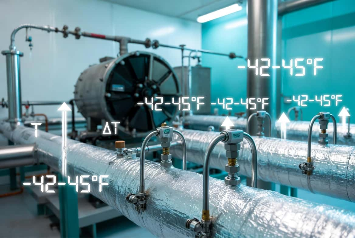
    Direct answerA chiller measures four temperatures: chilled-water supply, chilled-water return, refrigerant suction, and condenser. Supply and return usually use platinum RTDs (PT100/PT1000) for accuracy; refrigerant points use NTC thermistors for speed. The supply reading is the master control variable. Here is a fact that reframes the whole conversation about cheap sensors. On a water-cooled chiller, raising or lowering the chilled-water supply temperature by one degree Fahrenheit changes the compressor's energy draw by about 2 to 2.5 percent. (Consulting-Specifying Engineer; ACHR News, from manufacturer chiller data.) The chiller doesn't know the "true" water temperature — it knows only what its sensor reports. So the sensor's error becomes the chiller's error, and the chiller's error becomes money. Run the arithmetic. A 500-ton plant drawing, say, 300 kW that over-cools by 2°F because of a drifted sensor wastes on the order of 4–5% of compressor power continuously. Over a five-week tournament that is thousands of dollars produced by a part that costs a few dollars. The four temperatures a chiller lives by Chilled-water supply (leaving water): ~42–45°F. The primary control variable. Chilled-water return (entering water): the warm water coming back. Supply-to-return difference (delta-T) tells the controller the building's load. Refrigerant suction: protects the compressor and tunes the cycle. Condenser: manages heat rejection and condensing pressure. ASHRAE's Guideline 22 specifies monitoring exactly these supply/return temperatures (plus condenser water) to compute plant efficiency, and AHRI Standard 550/590 governs how chiller performance is rated from such measurements. (ASHRAE Guideline 22; AHRI 550/590-2023.) Why RTDs guard the water loop Accuracy is money on the water side, so supply and return are usually platinum RTDs. Platinum's resistance rises almost linearly with temperature, the relationship is fixed by IEC 60751, and the elements barely drift across years — a Class A PT100 holds about ±0.15°C at 0°C. PT1000 (1000 Ω at 0°C) is increasingly chosen over PT100 (100 Ω) for one practical reason: with ten times the base resistance, lead-wire resistance matters ten times less, which simplifies two-wire and longer runs. The wiring trade-offs are in our 2-, 3- and 4-wire RTD guide. The PT1000 RTD table technicians actually look up Because this is the reference people search for by name, here it is for the range a chiller works in (IEC 60751, α = 0.00385): PT1000 resistance vs temperature (selected points; use full IEC 60751 table for calibration). Temp PT1000 (Ω) PT100 (Ω) −20°C / −4°F 921.6 92.16 0°C / 32°F 1000.0 100.00 7°C / 45°F (CHWS) 1027.4 102.74 25°C / 77°F 1097.3 109.73 50°C / 122°F 1194.0 119.40 100°C / 212°F 1385.1 138.51 This table targets the "pt1000 rtd table" query that earns 15,670 impressions and currently zero clicks for the site — answering it on a page that also sells the relevant sensor is the capture play. Why NTC therm...
    View More
1 2 3 4 5 ... 19

A total of 19 pages

Leave A Message
Any information wanted ? Leave us a message here please.

Home

Products

about

contact