October 15, 2026
PTC thermistor for motor winding protection: wiring and selection
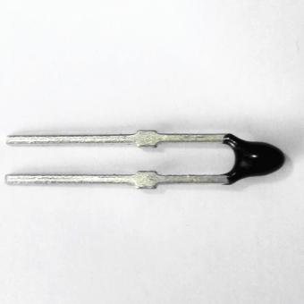
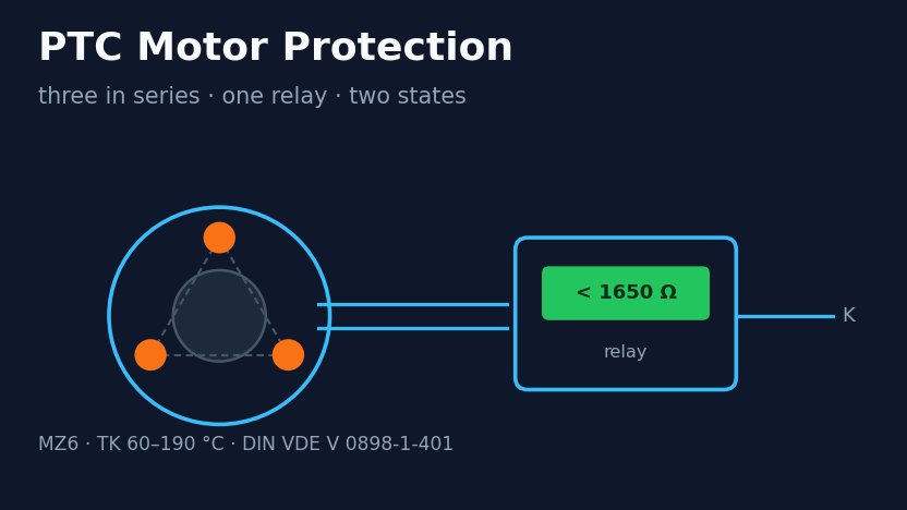
PTC Motor Thermistor for Winding Protection: Wiring and Trip Values A motor thermistor is a PTC sensor embedded in the stator winding, one per phase, with the three wired in series to a thermistor relay or a drive's PTC input. Each sensor stays between 20 and 250 Ω up to 20 K below its rated temperature (TNAT) and reaches at least 4000 Ω by TNAT + 15 K, the limits of DIN VDE V 0898-1-401 for rated temperatures of 90-160 °C. The four relays checked here (ABB, Crouzet, Schneider and ZIEHL) trip at 2.7-3.85 kΩ. All four are below 4000 Ω, so one overheated winding can drop the contactor on its own while the other two sensors are cold, but the DIN limits only guarantee that once its sensor reaches TNAT + 15 K; an even overload of all three is guaranteed to trip by TNAT + 5 K. Updated 15 October 2026: corrected how a three-sensor string trips, added relay trip values from four makers, and corrected the insulation-test guidance. First published 10 September 2026. Reviewed by the Focusens Engineering Team. Three PTC thermistors go into a three-phase motor, embedded in the winding heads and wired in series, so only two wires leave the motor. Below the rated temperature the string sits at a few hundred ohms. This page gives the resistance limits the sensors have to meet, the trip values of common relays, and what those two sets of numbers mean for how the string behaves and how many sensors one relay can read. Why a PTC and not a current-based relay A thermal overload relay infers winding temperature from line current. That inference holds while the motor is cooled normally and fails in the cases that actually burn windings: blocked ventilation, high ambient, a clogged filter, rapid start-stop duty, or a motor running at rated current in a hot room. Current looks normal. The winding does not. An embedded PTC measures the winding itself, so none of those cases hide from it. It does not replace a current-based device: it gives no protection against short circuits, and a current relay reacts directly to overcurrent such as a locked rotor. Standard practice is to run both. A PT100 in the winding gives a continuous temperature reading instead of a threshold, which is what you want on a large machine with a monitoring system. The PTC is a simpler last line of defence: the relay needs no scaling or calibration and the output has two states. The resistance limits a motor PTC has to meet A switching PTC is specified by its resistance at fixed offsets from its rated temperature, TNAT (the Focusens MZ6 datasheet writes TK). The limits come from DIN VDE V 0898-1-401, which replaced DIN 44081 and DIN 44082 in 2016, and they apply to rated temperatures from 90 to 160 °C. The values below are as published by Thermik and TDK, which agree: Temperature One sensor Three in series, all at the same temperature (3 × single limit, our calculation) Measuring voltage 25 °C (MZ6 rated resistance) ≤100 Ω ≤300 Ω ≤2.5 V -20 °C up to TNAT - 20 K 20-250 Ω 60-750 Ω ≤2.5 V TNAT - 5 K ≤550...
View More







 +86-551-69109668