September 24, 2026
10k Thermistor Chart: Type 2 vs Type 3 vs 3950 Tables
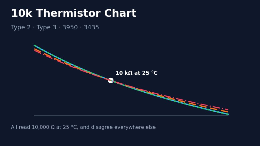
Short answer. A 10k NTC thermistor reads 10,000 Ω at 25 °C (77 °F), whichever curve it follows. Away from 25 °C the curves separate. At 0 °C a Type 2 reads 32,651 Ω, a Type 3 29,490 Ω, a 10k 3950 part about 32,755 Ω and a 10k 3435 part about 27,700 Ω. A 10k NTC thermistor reads 10,000 Ω at 25 °C (77 °F), whichever curve it follows. Away from 25 °C the curves separate. At 0 °C a Type 2 thermistor reads 32,651 Ω, a Type 3 reads 29,490 Ω, a 10k 3950 part reads about 32,755 Ω and a 10k 3435 part about 27,700 Ω. The chart below gives all four curves from −40 to 125 °C, followed by the error a controller shows when it expects one curve and gets another. Reviewed by the Focusens Engineering Team, 24 September 2026. 10k thermistor resistance chart, −40 to 125 °C °C °F Type 2 (10K3A1), Ω Type 3 (10K4A1), Ω 10k 3950, Ω 10k 3435, Ω −40 −40 336,098 239,828 343,633 204,700 −30 −22 176,803 135,233 179,267 118,500 −20 −4 97,006 78,930 97,840 71,020 −10 14 55,304 47,549 55,595 43,670 0 32 32,651 29,490 32,755 27,700 10 50 19,903 18,787 19,938 18,070 20 68 12,493 12,268 12,501 12,110 25 77 10,000 10,000 10,000 10,000 30 86 8,056 8,196 8,051 8,301 40 104 5,325 5,594 5,315 5,811 50 122 3,601 3,893 3,588 4,147 60 140 2,487 2,760 2,473 3,011 70 158 1,752 1,990 1,738 2,224 80 176 1,256 1,458 1,243 1,668 90 194 916 1,084 904 1,267 100 212 678 817 668 975 110 230 510 624 500 760 120 248 388 482 380 598 125 257 341 426 333 533 Sources, one per column. Type 2: Measurement Specialties (now TE Connectivity) 10K3A1 datasheet. Type 3: TE Connectivity 10K4A1 datasheet. Both columns agree with Vishay Curve 1 and Curve 9 in the Vishay NTC resistance/temperature conversion tables to within 0.3%, under 0.1 K, from −20 to 100 °C. 10k 3950: typical values from the Zhuhai Hongjiacheng HNTC-103F3950FB datasheet, a B25/50 = 3950 K material, rounded to the ohm. 10k 3435: Semitec 103JT datasheet, B25/85 = 3435 K, rounded to the ohm. Fahrenheit values are converted and rounded to the whole degree. The 3950 and 3435 columns each come from one manufacturer's material. Other materials sold under the same beta number follow a slightly different curve, because a beta value fixes two points and the rest of the curve depends on the ceramic. Plotted from the datasheet values in the table above. The lower panel is the same four curves measured against Type 2. Ask for the part's own resistance table; the beta alone does not define it. Which curve is which: Type 2, Type 3, 3950 and 3435 "Type 2" and "Type 3" are building-automation names, not a standard. In many North American HVAC output tables, a table labelled 10K-2 or Type II carries the values of the 10K3A1 curve (Vishay Curve 1), and a table labelled 10K-3 or Type III carries the 10K4A1 curve (Vishay Curve 9). The beta values below put all four materials on the same footing. Common name Element curve Published beta B25/50 B25/85 B0/50 10K Type 2 (10K-2, Type II) 10K3A1, Vishay Curve 1 B25/85 = 3976 K 3936 K 3977 K 3892 K 10K Type 3 (10K-3, Typ...
View More







 +86-551-69109668