other
  • Operating Precautions for Temperature Transmitters
    June 21, 2022 Operating Precautions for Temperature Transmitters
    The temperature transmitter technology has been very mature, and it is very common in various factories. The temperature transmitter is often used in conjunction with some instruments, and there are often some small faults during the supporting use. The more common faults and solutions are as follows. First, the output of the transmitter does not change when the temperature of the measured medium increases or decreases. Most of these cases are caused by the sealing of the temperature transmitter. It may be because the temperature transmitter is not sealed well or is careless during welding. The sensor is welded with a small hole, which generally requires replacing the transmitter housing to solve. Second, the output signal is unstable. This reason is the reason of the temperature source, which is an unstable temperature. If the instrument display is unstable, it is the reason that the anti-interference ability of the instrument is not strong. Third, the output error of the transmitter is large, and there are many reasons for this situation. It may be that the resistance wire of the selected temperature transmitter is not correct, resulting in a wrong range, or it may be that the transmitter is not calibrated well when it leaves the factory.
    View More
  • Master Worker Appointment Ceremoney
    February 26, 2022 Master Worker Appointment Ceremoney
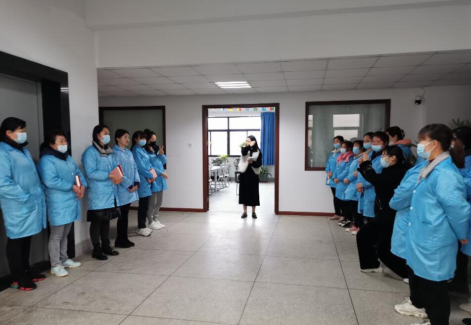
    In order to give full play to the "passing, helping, and leading" role of the backbone of the enterprise and accelerate the growth of new employees, the company recently organized a "teacher and apprentice" activity. Six Workers were successfully elected as masters after working skill competition . Today the company hold ceremoney to awarded the these expert staff as Master. In order to ensure the effect of the activity, the company strictly controls the selection of masters. Based on the standards of excellent professional ethics, rich work experience, superb business skills, and outstanding work efficiency, the company selects key employees as "masters" and "apprentices" with 3 new employees. Pair-by-pair apprenticeships further clarified the training goals and the responsibilities and obligations of both teachers and apprentices. At the same time, the company formulates detailed training plans and assessment methods for new NTC thermistor manufacturing employees, which will be assessed in terms of attendance rate, work attitude, job responsibilities, practical efficiency, work quality, etc. New employees should master the post business knowledge and relevant management knowledge as soon as possible, strive to become talents as soon as possible, and make due contributions to the development of the company. The launch of the "Teacher and Apprentice" activity has built a good communication bridge and exchange platform for the company's new and old employees, which is conducive to promoting new employees to integrate into the company as soon as possible, complete the role change, and achieve the improvement of skills and quality, which will help the company improve. Quality development injects new vitality.
    View More
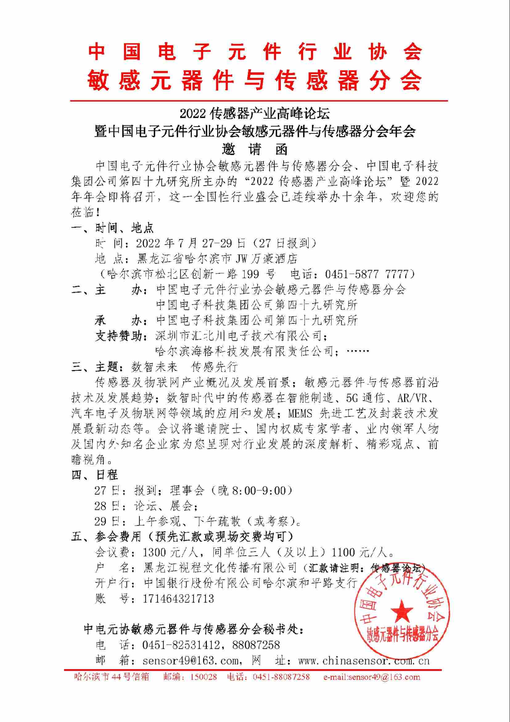
  • 2022 Sensor Industry Summit Forum Invitation Letter
  • Dragon Boat Festival holiday notice
    June 06, 2022 Dragon Boat Festival holiday notice
    June 3rd - -June 5th holiday, a total of 3 days This holiday adjustment will be adjusted according to the weekend Notice hereby!
    View More
  • How to Test a Thermocouple with a Multimeter: 5 Steps
    August 27, 2026 How to Test a Thermocouple with a Multimeter: 5 Steps
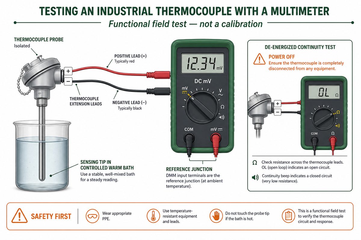
    A practical thermocouple test has two parts: check the de-energized circuit for a break, then check whether the sensor produces a smooth, correctly directed DC millivolt change when its measuring junction is heated or cooled. A multimeter can find many field faults, but it cannot by itself prove calibration accuracy. This guide is for industrial J-, K-, T-, E-, N- and S-type thermocouple probes and their wiring. It does not apply a gas-valve thermocouple's appliance-specific millivolt criterion to industrial temperature probes. For an industrial probe, the expected voltage depends on thermocouple type, measuring-junction temperature and reference-junction temperature. Separate the de-energized continuity check from the powered-system and dynamic mV checks. What you need before testing Identify the thermocouple and the receiving instrument before touching the leads. You need a multimeter with DC millivolt and resistance/continuity modes, insulated test leads or the correct thermocouple adapter, a controlled heat or cold source, the thermocouple type/polarity information, and the transmitter or controller manual. Unknown wiring makes a voltage reading ambiguous. Follow the equipment's shutdown, lockout and process-isolation procedure. Never select resistance or continuity mode on an energized circuit. Fluke's multimeter guidance requires circuit power to be disconnected before continuity testing. Record the thermocouple type, wire polarity, terminal numbers, extension-wire type and current instrument configuration before disconnecting anything. Inspect for loose terminals, corrosion, crushed cable, damaged insulation, moisture and an exposed or displaced measuring junction. Determine whether the probe is grounded, ungrounded or exposed if that construction affects your continuity-to-sheath test. Use a controlled bath, dry-block or other source that stays within the probe's approved limits. A lighter or torch is not a universal test source for an industrial probe. If the thermocouple is installed in a hazardous, pressurized or high-temperature process, stop at the approved test point. A multimeter procedure does not replace the plant's safe-work method or the equipment manufacturer's instructions. How to test a thermocouple with a multimeter in five steps The five-step sequence is: identify and isolate the circuit, inspect it, screen it for continuity, establish a raw-mV baseline, then apply a controlled temperature change and isolate the remaining signal path. Keep the test conditions with the reading. A number without thermocouple type and reference-junction temperature cannot be interpreted reliably. Step 1: Identify the type, polarity and test boundary Confirm whether the sensor is J, K, T, E, N, S or another type. Photograph or label the terminals before removal. Decide whether you are testing only the probe, the probe plus extension cable, or the complete sensor-to-transmitter path. Then isolate that boundary according to the equipment manual....
    View More

  • RTD Probe Sheath Material and Structure Selection Guide
    August 25, 2026 RTD Probe Sheath Material and Structure Selection Guide
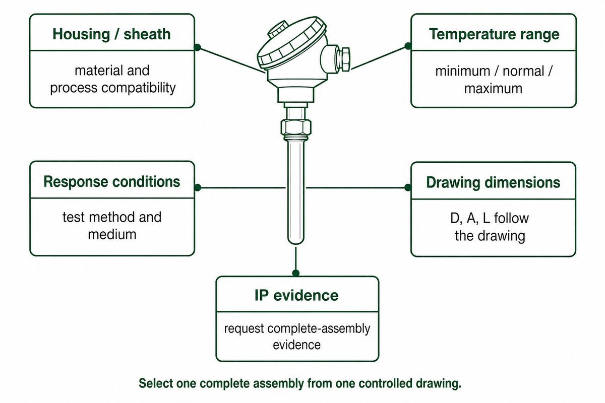
    The safest way to select an RTD probe is to match one documented construction to the process, not to apply a family maximum to every probe. In the Focusens FWZ Series source, SUS304 and SUS316 are listed housing materials. The family technical table lists -50 to +200°C, -50 to +350°C and -50 to +600°C ranges, plus a 10 s response entry labelled 0.63τ. Individual drawings are more specific: they show -50 to +200°C through -50 to +500°C, diameters from 3 to 16 mm, customer-defined lengths, and 20 or 30 s response entries in still air. Those values are useful only with their original conditions. The FWZ pages do not provide a common t50/t90 comparison, a material-specific corrosion envelope, or an IP65/IP67 rating. Inconel 600, Hastelloy, a PTFE probe sheath and a mineral-insulated FWZ construction are also not listed as standard options in the reviewed FWZ pages. Treat those as engineered requests, not published Focusens specifications. Select the complete assembly from a controlled drawing; do not combine unrelated family maximums. What is included in an RTD probe? An RTD sensor is the resistance-based sensing element. An RTD probe is an assembly that can include the element, a sheath or housing, filler or insulation, extension leads and a connector or termination. TE Connectivity's RTD overview makes the same element-versus-assembly distinction. This distinction affects every purchasing decision. A Teflon lead-wire option does not prove that the wetted probe has a PTFE sheath. A housing material does not define the cable limit. A terminal head rating does not automatically cover the gland, connector and installed assembly. The Focusens FWZ ordering code lists Pt100, Pt1000, Cu500 and Ni element choices, DIN Class A, B, C or a special class, simplex or duplex construction, eight mounting categories, five wire-material categories and a customer-defined wire length. The technical table separately lists PT100, PT500 and PT1000. Confirm the final element and accuracy class on the quotation and drawing when these two source sections are used together. Focusens FWZ specifications available from the supplied catalogue Selection field FWZ source entry How to use it RTD element Technical table: PT100, PT500, PT1000. Ordering code: Pt100, Pt1000, Cu500, Ni Match the selected code to the controller input and approved drawing Accuracy DIN Class A or B in the technical table; Class A/B/C/special in the ordering code Do not claim one class for every model; specify it in the order code Housing SUS304 or SUS316 These are documented housing choices, but no separate temperature or corrosion envelope is assigned to either material Family measuring bands -50 to +200°C, -50 to +350°C, -50 to +600°C Family-level choices; the selected drawing can have a lower maximum General response entry 10 s (0.63τ) Preserve this exact definition; do not relabel it as t50 or t90 Drawing-specific response 20 or 30 s in still air Compare only drawings tested and reported on the same ba...
    View More
  • 347
    December 08, 2025 347
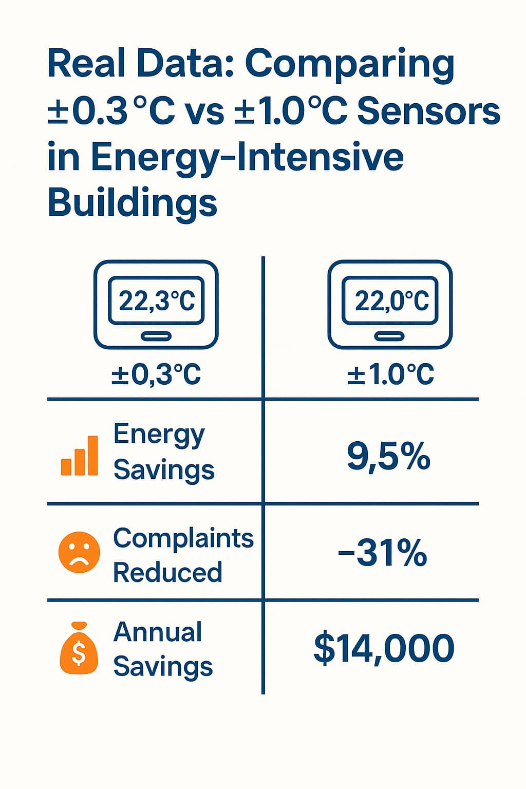
    TemperatureSensor & HVAC Sensors Insights — Precision Matters in Smart HVAC Real Data: Comparing ±0.3 °C vs ±1.0 °C Sensors in Energy-Intensive Buildings 1. Temperature Accuracy: The Invisible Backbone of Indoor Comfort Central air conditioning in homes and businesses offers comfort that goes beyond just temperature. This sentence discusses how consistently and accurately someone keeps the environment. The human body can sense temperature changes as small as 0.3 °C. This is especially true in places like offices, hotels, and luxury homes. When a thermostat or sensor is off by 1.0 °C, the system overreacts — this causes uncomfortable temperature changes, wastes energy, and leaves people unhappy. That's why the difference between a ±1.0 °C sensor and a ±0.3 °C sensor is important — crucial for any serious HVAC or Smart HVAC system. 2. Homogenized HVAC Market Needs Real Differentiation Today, many HVAC systems offer similar core features — heating, cooling, and basic automation. In a crowded and similar industry, what makes a system stand out is what it senses — including the accuracy of the TemperatureSensor. High-precision sensors, often underestimated, directly impact system responsiveness, energy usage, and long-term performance. The following real-world examples highlight the performance gap. Real-World Case Studies: Performance Gains from Precision Sensors Case Scenario What Changed After Upgrading to ±0.3 °C Sensors Residential Villa – Vancouver, Canada High-end villa installation 31% reduction in climate-related complaints; lower system cycling frequency; homeowner comfort rated 4.7/5 Hospital HVAC Retrofit – Seoul, South Korea Operating rooms / medical-grade HVAC Achieved ±0.2 °C environment stability; HVAC fluctuations reduced by 42%; better compliance with medical-grade standards Office Complex – Munich, Germany Commercial office HVAC ±1.0 °C → ±0.3 °C: 9.5% annual energy savings (~€18,000); improved employee productivity; HVAC downtime reduced by 17% 5-Star Hotel Chain – Singapore Guest rooms & hospitality HVAC Improved “room climate” review scores; lower chiller workload during peak months; ~US $11,000 annual savings per property Industry reports show that a misreading of just 0.5 °C can cause energy overuse — up to 8% — in energy-intensive zones like commercial kitchens and data centers. Precision — not just features — underlies real energy efficiency and comfort. 3. Five Smart Ways to Build HVAC Differentiation in a Saturated Market Use high-accuracy sensors (±0.3 °C or better) — reduces energy waste while improving occupant comfort. Integrate with IoT & BMS platforms — real-time sensor feedback enables predictive control and smarter climate regulation. Zone-based temperature mapping — personalized comfort per room or zone enhances occupant satisfaction and efficiency. Pair temperature sensors with smart humidity sensors — prevents mold, discomfort, and reduces maintenance costs. Focus on retrofit-friendly and scalable design — system...
    View More
  • What Is the temperature range of the NTC 10k?
    October 13, 2025 What Is the temperature range of the NTC 10k?
    Focusensing Releases Advanced 10k NTC Thermistor Series with Enhanced Stability & Automotive-Grade Quality body { font-family: Arial, sans-serif; line-height: 1.6; color: #222; max-width: 900px; margin: auto; padding: 24px; } h1, h2, h3 { color: #0a3c6e; } .lead { background: #f4f8fc; border-left: 4px solid #0a5fae; padding: 12px 16px; margin-bottom: 20px; } table { width: 100%; border-collapse: collapse; margin: 16px 0; } table th, table td { border: 1px solid #cfd8e0; padding: 8px; } .chart-placeholder { background: #fafafa; border: 1px dashed #c0cbd3; padding: 24px; text-align: center; margin: 20px 0; color: #666; } .product-box { border: 1px solid #dce6f0; padding: 16px; border-radius: 6px; background: #f9fcfe; margin: 20px 0; } .cta { display: inline-block; background: #0a5fae; color: #fff; text-decoration: none; padding: 10px 16px; border-radius: 4px; margin-top: 12px; } .refs { font-size: 0.9rem; color: #555; margin-top: 32px; } In 2025, Focusensing launches its new 10k NTC thermistor line. These thermistors have tighter tolerance, lower drift, and strong packaging. They are made for tough sectors like EV battery systems, HVAC, and IoT.Explore features, datasheet support, and application guidance below. 1. The Role of 10k NTC Thermistors in Modern Temperature Sensing In 2025, 10k NTC thermistors are still a top choice for designers. They offer great sensitivity, cost-effectiveness, and compatibility with electronic systems.The “10k” refers to the nominal resistance at 25 °C—i.e. R25 = 10,000 Ω. This base point allows standardization across many applications.  NTC thermistors are negative temperature coefficient resistors: as temperature increases, resistance decreases.This behavior is sharper than metals or silicon resistors. It makes them very sensitive in many thermal monitoring tasks.  2. R-T Behavior & Modeling with Public Data A widely used reference is the Labfacility 10k NTC table (B25/85 = 3977 K), which maps temperature to resistance across –40 °C to +125 °C. Temperature (°C) Resistance (kΩ) –40 336.479 0 32.65 (approx) 25 10.00 50 3.747 90 0.916 This nonlinear response is typically modeled via the B-parameter or the Steinhart–Hart equation. For instance, Electronics Tutorials uses B = 3455 for a 10k NTC spanning 25 °C to 100 °C. ([electronics-tutorials.ws] 3. Critical Parameter Considerations 3.1 Tolerance & Beta Stability Common tolerances include ±1 %, ±2 %, ±5 %. For example, Amwei’s 10k device lists R25 ±1 % with Beta B25/85 = 3435 K ±1 %. [amwei.com] Stability of the Beta parameter over time and environmental cycling is crucial for long-term accuracy. 3.2 Thermal Time Constant & Self-Heating The thermal time constant for many 10k NTC units is around 10–15 seconds. For instance, Handson’s 10k-3950 spec sheet lists 15 s.Meanwhile, self-heating (due to the measuring current) can artificially raise the sensor’s temperature and distort readings. Designers must restrict excitation current to limit the error to acceptable levels. 3...
    View More
1 ... 14 15 16 17 18

A total of 18 pages

Leave A Message
Any information wanted ? Leave us a message here please.

Home

Products

about

contact