October 01, 2026
2-Wire vs 3-Wire vs 4-Wire RTD: Understanding PT100 & PT1000 Sensor Accuracy
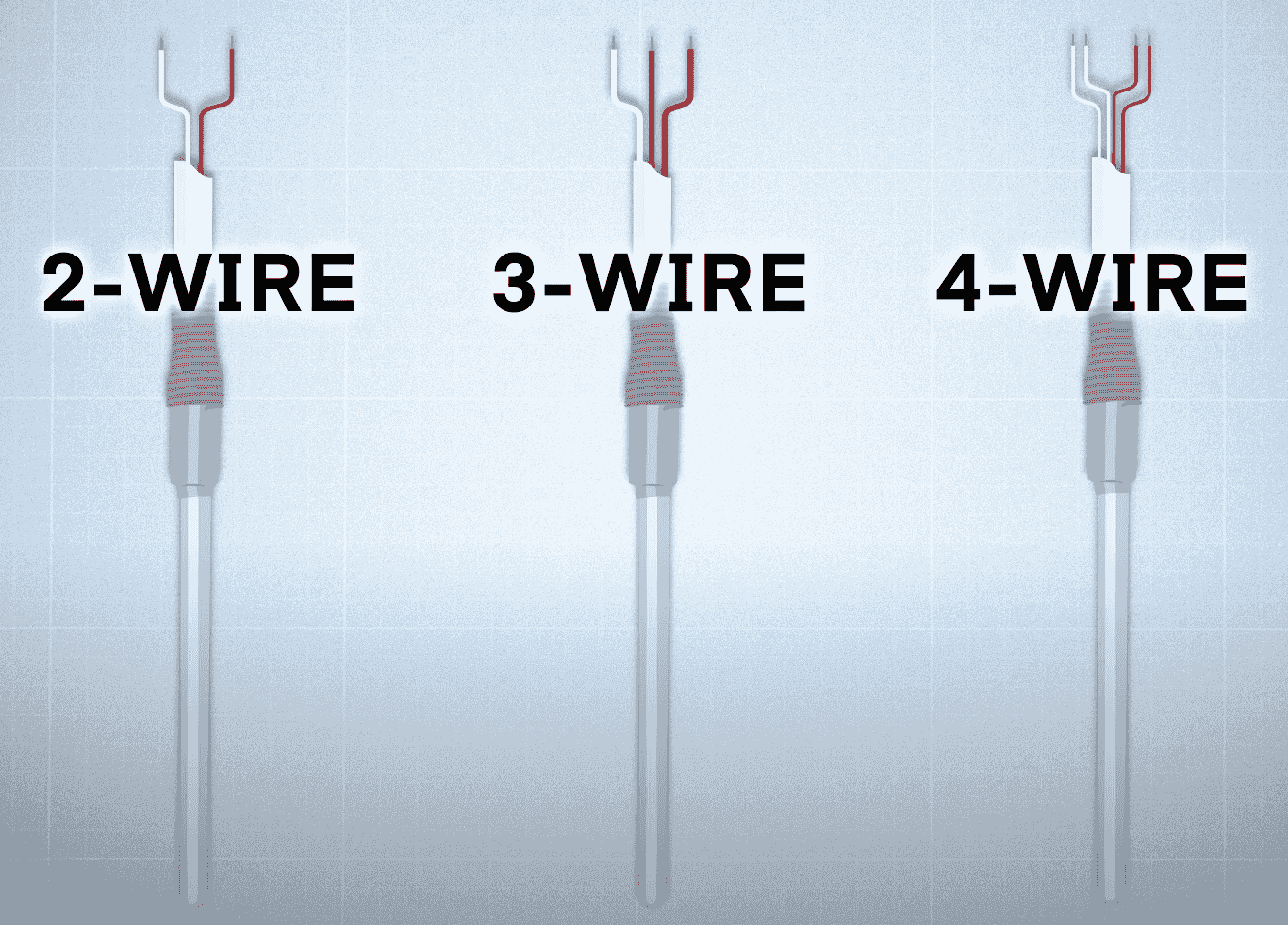
PT100/PT1000 RTD Wiring: 2 vs 3 vs 4-Wire and Color Codes On a 3-wire RTD, the two leads from the same end of the element go to one current terminal and the sense terminal paired with it, and the single lead goes to the other current terminal; the input manual shows which terminals pair up (EXC and SENSE on a Rockwell 1769-IR6, M− and Ic− on a Siemens S7-1500 RTD input). In the example scheme of IEC 60751:2022 (Figure 1), leads of the same color connect to the same end of the element, so a 3-wire PT100 or PT1000 has two red leads on one end and one white lead on the other. Manufacturers do not all follow it, so confirm with a multimeter before you connect: two leads from the same end read close to 0 Ω, and leads from opposite ends read the element, about 109.7 Ω for a PT100 at 25 °C and about 1097 Ω for a PT1000. Updated October 1, 2026. Reviewed by the Focusens Engineering Team. 2-wire, 3-wire and 4-wire RTD wiring diagrams Configuration Leads How it connects What it does about lead resistance 2-wire One lead at each end of the element Both leads carry the excitation current and are also the measurement leads Nothing; both leads add to the reading 3-wire Two leads at one end, one at the other The extra lead lets the instrument measure one lead and subtract it Cancels the lead resistance as long as the leads match 4-wire Two leads at each end One pair carries the current, the other pair measures the voltage across the element Removes lead resistance from the measurement Illustration. Same-color leads join the same end of the element. IEC 60751:2022, the international standard for industrial platinum RTDs, ties accuracy to the wiring. Clause 5.5 states that thermometers of a tolerance class "better than class B shall have 3-wire or 4-wire configuration", with the "4-wire configuration being recommended" (IEC 60751:2022 preview, IEC webstore). Under IEC 60751:2022, a 2-wire probe therefore cannot be declared better than Class B, even if the element inside it is Class A or AA. 3-wire is the industrial default because it removes most of the lead error with one extra conductor. Its limit is that it assumes the leads are identical; Emerson's Rosemount 248 manual notes that a 3-wire connection "cannot compensate for imbalances". How large that imbalance error gets, and how much 2-wire cable adds, is worked through in our page on RTD lead resistance error. Thermistors are far less sensitive to cable: a 10 kΩ NTC moves about 0.002 °C per ohm at 25 °C, as shown in our thermistor wiring guide. RTD wire color codes, and why colors alone are not proof In the IEC 60751:2022 example, leads at the same end of the element share a color. Configuration IEC 60751:2022 Figure 1 (also Emerson 214C, JIS C 1604) Second element in a duplex probe 2-wire Red, white Black, yellow 3-wire Red, red, white Black, black, yellow 4-wire Red, red, white, white Black, black, yellow, yellow Figure 1 of the standard covers one and two elements, with "Black (Grey)" for the second eleme...
View More







 +86-551-69109668