How to test a KTY84-130 with a multimeter: what 603 ohm at 25 C actually proves
Sep 16, 2026The most-read question about this sensor on NXP's own community is some version of "how do I tell whether it still works". The published answer points at Table 7 of the data sheet and warns not to exceed 10 mA.
That is correct, and it is not enough. A table of nominal values does not tell you which readings mean a dead part, which mean the wrong part, and which mean the wiring.
This page fills in that gap.
NXP publishes an acceptance window, not just a nominal curve. Table 7 of the data sheet gives minimum, typical and maximum resistance at every step from -40 to 300 °C. It lives in a PDF, which is why most people quote the typical column and stop there.
Here is the window itself, for the KTY84/130.
| Temperature (°C) | Min (Ω) | Typ (Ω) | Max (Ω) | TC (%/K) |
|---|---|---|---|---|
| -40 | 340 | 359 | 379 | 0.84 |
| 0 | 474 | 498 | 522 | 0.79 |
| 25 | 577 | 603 | 629 | 0.74 |
| 100 | 970 | 1000 | 1030 | 0.61 |
| 150 | 1282 | 1334 | 1385 | 0.54 |
| 200 | 1641 | 1722 | 1803 | 0.48 |
| 250 | 2046 | 2166 | 2286 | 0.44 |
| 300 | 2456 | 2624 | 2791 | 0.29 |
KTY84/130 at a 2 mA sense current, from Table 7 of the NXP KTY84 series data sheet. Bold rows are the two measurements that decide most questions.
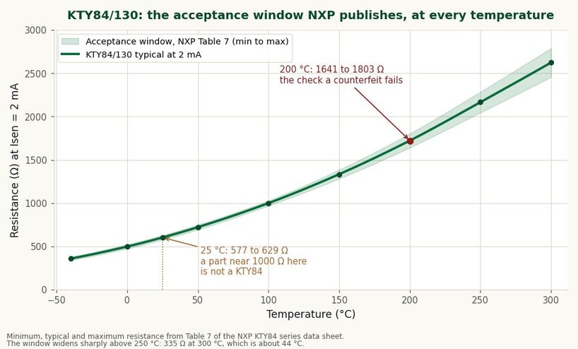
The shaded band is what a good part is allowed to read. Note how much it widens above 150 °C.
The last column is the one to notice. The temperature coefficient falls steadily with temperature, and then drops sharply between 250 and 300 °C, from 0.44 to 0.29 %/K. The curve flattens at the very top of the range.
That has a practical consequence. Near 25 °C the part moves about 4.6 Ω per degree, so a 10 Ω reading error is roughly 2 °C. At 300 °C the acceptance window itself is 335 Ω wide, which is about 44 °C. A KTY84 used at its ceiling is not a precision sensor, whatever its grade.
Every figure above is specified at a 2 mA sense current. A handheld meter on its ohms range does not supply 2 mA. It supplies whatever its own design chooses, typically well under 1 mA, and it does not tell you what that is.
This is not small print for a KTY sensor. The data sheet carries a curve for it. Figure 4, "deviation of sensor resistance as a function of operating current in still liquid", has separate traces at 2 mA, 1 mA, 0.5 mA and minus 1 mA.
The dependence is real and published. What is not published is a correction table.
Self-heating pushes the same way. At 2 mA through 603 Ω the sensor dissipates about 2.4 mW, and NXP's own thermal time constant is 20 s in still air. Take the reading after the number settles, not while it is still drifting upward.
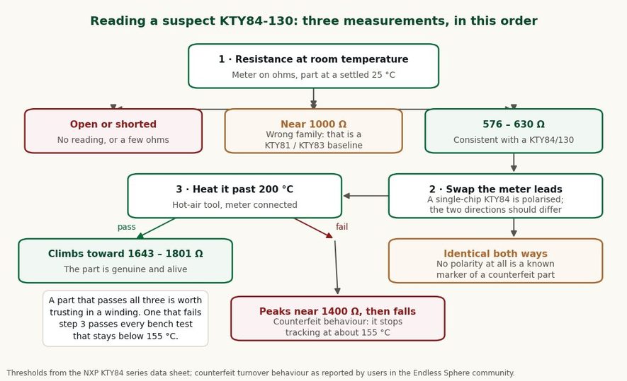
Each step rules out a different failure. Step 3 is the one most people skip, and the only one a counterfeit fails.
Let the part sit until it is genuinely at ambient, then read it. Three outcomes are worth naming separately.
Open circuit, or a few ohms, means a broken element or a broken joint. A reading near 1000 Ω means the part is not a KTY84 at all. That is the KTY81 and KTY83 baseline, specified at 25 °C rather than at 100 °C.
A reading of 577-629 Ω is consistent with a KTY84/130. It is not yet proof, which is what steps 2 and 3 are for.
The baseline confusion is common enough that it has its own section in the KTY84 replacement guide, and the part-by-part mapping is in the KTY83-110 cross-reference guide.
KTY83 and KTY84 are single-chip sensors and they are polarised. Philips stated it plainly: the published characteristics are only obtained if the current polarity is correct. KTY81 and KTY82 use two chips in series opposed and do not care about direction.
So on a genuine KTY84 the two directions should not read identically. Parts reported as counterfeit show no polarity at all and carry no coloured band. If your sample reads the same both ways and has no band, treat the whole batch as suspect before step 3 rather than after it.
A hot-air tool and a clip-on meter are enough. The resistance must keep climbing, through roughly 1334 Ω at 150 °C and on toward 1722 Ω at 200 °C.
Counterfeit parts track correctly up to about 1400 Ω, which is near 155 °C, and then turn over: resistance starts falling as the part gets hotter. A winding at a true 180 °C then reports a comfortable number and nothing trips.
This is the reason step 3 cannot be skipped. Every test that stays below 155 °C passes on a counterfeit part, so the usual incoming inspection (read it at room temperature, warm it with a finger, watch it move) proves nothing about the range where the sensor is actually doing its job.
| Reading | What it means | What to do |
|---|---|---|
| No continuity | Broken element or an open joint | Check the leads at the glass seal before condemning the part |
| Under 50 Ω | Short, usually in the harness | Disconnect at the sensor and re-read at the part itself |
| 950-1050 Ω at 25 °C | A KTY81 or KTY83, not a KTY84 | Different baseline; the controller table will not match |
| 577-629 Ω at 25 °C | Consistent with KTY84/130 | Continue to steps 2 and 3 |
| Same reading in both lead directions | No polarity, a counterfeit marker | Check for the coloured band; heat-test before use |
| Climbs, then falls above ~1400 Ω | Counterfeit turnover near 155 °C | Reject the batch; it reads low exactly when it matters |
| Reading jumps or drifts with the cable moved | Not the sensor | Wiring, connector or lead resistance |
The last row is worth the time it takes. A sensor that reads differently when someone touches the cable has never been the problem, and swapping it costs a part and a shutdown without fixing anything.
NXP's guidance is a current limit rather than a voltage: 10 mA continuous at 25 °C, falling to 2 mA at 300 °C. At the low end of the range, where the part is near 340 Ω, 10 mA corresponds to about 3.4 V across it.
A 5 V rail with a series resistor is the usual bench arrangement. With a 4.7 kΩ series resistor the sensor current stays around 0.9-1 mA across the whole range, which is inside the limit at every temperature and close enough to the 1 mA trace in the data sheet to be useful.
| Temperature (°C) | Sensor R (Ω) | Current (mA) | Voltage across sensor (V) |
|---|---|---|---|
| 25 | 603 | 0.94 | 0.57 |
| 100 | 1000 | 0.88 | 0.88 |
| 150 | 1334 | 0.82 | 1.10 |
| 200 | 1722 | 0.78 | 1.34 |
| 300 | 2624 | 0.68 | 1.79 |
A 5 V supply through a 4.7 kΩ series resistor. Current stays under 1 mA at every point, well inside the 2 mA limit that applies at 300 °C.
Two lead wires of ordinary harness cable can add a couple of ohms, and at 4.6 Ω per degree near room temperature that is under a degree of error.
Lead resistance is rarely the culprit with a KTY part. That is the opposite of a 100 Ω platinum RTD, where 1 Ω of lead is about 2.56 °C. The PT100 resistance tables show why.
What does cause trouble, in rough order of frequency:
The same ordering logic applies to other element types. The NTC multimeter test and the PTC check procedure cover those. For winding protection specifically, where a switching PTC and a linear sensor do genuinely different jobs, start with the motor winding protection guide.
577-629 Ω at 25 °C. Roughly 1000 Ω is the 100 °C value, not the room-temperature one.
Yes, for a pass or fail judgement. Not for calibration: the data-sheet values assume a 2 mA sense current and a handheld meter supplies something lower and unstated, so expect a small offset from the table.
On a KTY84 it does. It is a single-chip polarised sensor and the published curve only holds with the correct current direction. A part that reads identically in both directions is worth a second look.
Past 155 °C, and ideally to 200 °C where a good part reads 1641-1803 Ω. Below 155 °C a counterfeit tracks correctly and passes.
Almost certainly not. That is inside the combined effect of tolerance and the meter's own sense current. A part that is genuinely wrong is usually wrong by tens of percent, or it fails the heat test.
No.1 XiSan Road, Electromechanical Industry Park , High&New Tech.Zone. Hefei,Anhui,China
Tel : +86-551-69109668
Whatsapp : +86-13339100504
Email : info@focusens.com
Skype : melodyliu520






 +86-551-69109668