PTC thermistor for motor winding protection: wiring and selection
Oct 15, 2026Updated 15 October 2026: corrected how a three-sensor string trips, added relay trip values from four makers, and corrected the insulation-test guidance. First published 10 September 2026. Reviewed by the Focusens Engineering Team.
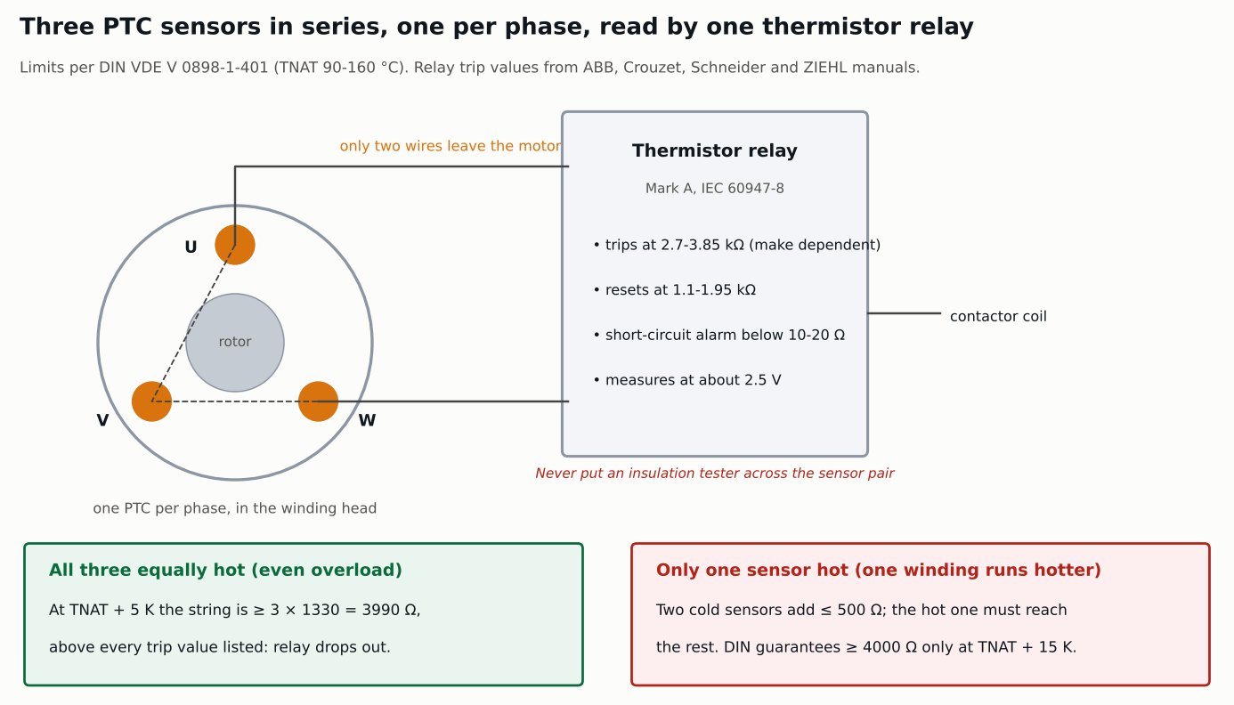
Three PTC thermistors go into a three-phase motor, embedded in the winding heads and wired in series, so only two wires leave the motor. Below the rated temperature the string sits at a few hundred ohms. This page gives the resistance limits the sensors have to meet, the trip values of common relays, and what those two sets of numbers mean for how the string behaves and how many sensors one relay can read.
A thermal overload relay infers winding temperature from line current. That inference holds while the motor is cooled normally and fails in the cases that actually burn windings: blocked ventilation, high ambient, a clogged filter, rapid start-stop duty, or a motor running at rated current in a hot room. Current looks normal. The winding does not.
An embedded PTC measures the winding itself, so none of those cases hide from it. It does not replace a current-based device: it gives no protection against short circuits, and a current relay reacts directly to overcurrent such as a locked rotor. Standard practice is to run both.
A PT100 in the winding gives a continuous temperature reading instead of a threshold, which is what you want on a large machine with a monitoring system. The PTC is a simpler last line of defence: the relay needs no scaling or calibration and the output has two states.
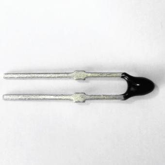
A switching PTC is specified by its resistance at fixed offsets from its rated temperature, TNAT (the Focusens MZ6 datasheet writes TK). The limits come from DIN VDE V 0898-1-401, which replaced DIN 44081 and DIN 44082 in 2016, and they apply to rated temperatures from 90 to 160 °C. The values below are as published by Thermik and TDK, which agree:
| Temperature | One sensor | Three in series, all at the same temperature (3 × single limit, our calculation) | Measuring voltage |
|---|---|---|---|
| 25 °C (MZ6 rated resistance) | ≤100 Ω | ≤300 Ω | ≤2.5 V |
| -20 °C up to TNAT - 20 K | 20-250 Ω | 60-750 Ω | ≤2.5 V |
| TNAT - 5 K | ≤550 Ω | ≤1650 Ω | ≤2.5 V |
| TNAT + 5 K | ≥1330 Ω | ≥3990 Ω | ≤2.5 V |
| TNAT + 15 K | ≥4000 Ω | ≥12 kΩ | ≤7.5 V, pulsed |
Rated points of 60-85 °C and 165-190 °C use a different threshold set with a wider band. For those, read the datasheet row for the TNAT you order.
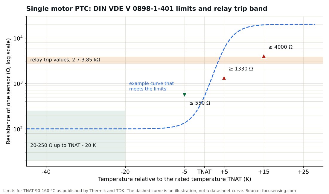
The right-hand column of that table is the single-sensor column times three. That only holds when all three sensors are at the same temperature, as in an even overload. In that case the string passes 3990 Ω at TNAT + 5 K, above the trip value of every relay in the next table, and the contactor drops. ZIEHL, which writes TNF for TNAT, gives the same picture from the relay side: one sensor trips at TNF + 15 K, three in series at TNF + 5 K and six in series at TNF.
The case that matters more is one winding running hotter than the other two. The relay then sees one hot sensor plus two cold ones, which together add 500 Ω at most, so the hot sensor has to climb past the rest of the trip value on its own. DIN guarantees 4000 Ω only at TNAT + 15 K, and every relay trip value below is under 4000 Ω. By our calculation from the published limits, a single hot winding is guaranteed to trip by TNAT + 15 K; at TNAT + 5 K a trip is possible but not guaranteed. Cantherm's triple-sensor table makes the same allowance, noting that one PTC might reach TNAT + 15 K while the others are still at room temperature. This holds for rated temperatures of 90-160 °C. Outside that range the datasheet limits differ (TDK, for example, guarantees 10 kΩ only at TNAT + 23 K for its 170 and 180 °C types), so redo the check with the limits for the TNAT you order.
| Relay | Trips at | Resets at | Short-circuit alarm | Cold string limit | Sensors in series |
|---|---|---|---|---|---|
| ABB CM-MSS.32 / .33 | 2.83 kΩ ±1 % | 1.1 kΩ ±1 % | below 12 Ω | below 750 Ω | 2 (3 × 250 Ω reaches the 750 Ω limit; our calculation) |
| Crouzet ETM 84874013 | 3.1 kΩ ±10 % | 1.65 kΩ ±10 % | 0-10 Ω | 1500 Ω | 6, with no allowance for cable (our calculation) |
| Schneider TeSys LT3SA00M | 2.7-3.1 kΩ | 1.5-1.65 kΩ | below 20 Ω | not stated | up to 6 (stated) |
| ZIEHL MS220KA | 3.3-3.85 kΩ | 1.7-1.95 kΩ | 20 Ω or less | 1.65 kΩ | 1, 3 or 6 (stated) |
From each maker's manual or datasheet: ABB 2CDC 112 221 D0201 Rev. F (2018), Crouzet ETM datasheet (2015), Schneider product datasheet (2017), ZIEHL MS220KA manual (2024).
Trip values run from 2.7 to 3.85 kΩ across these four, and none of them is 4 kΩ. The 4 kΩ figure that circulates is what the sensor guarantees at TNAT + 15 K, not a relay setting. To size a string, take the relay's cold-string limit, subtract the cable loop resistance, and divide by 250 Ω, the DIN worst case for one cold sensor. All four relays also alarm on a shorted sensor circuit, which a plain resistance threshold would read as a cold motor.
These relays read "Mark A" sensors, the interchangeable PTC detector that IEC 60034-11 builds into the machine and IEC 60947-8 pairs with a control unit. Many variable-speed drives have their own PTC input, which replaces the separate relay; its trip value is in the drive manual.
The 25 °C row is the row people test against, and it is the least informative one on the page. Cold resistance is specified only as a range or a maximum, ≤100 Ω for a single MZ6 element and ≤300 Ω for a string, and a healthy element and a marginal one both sit inside it. Cantherm says as much in its PTC datasheet: resistance when cold is no indication of the PTC's condition.
Nothing about the value at 25 °C predicts whether the step will land where it should, because the step is a property of the ceramic's transition and the cold state is far away from it. A goods-inwards check at room temperature confirms continuity and nothing else. A bench test proves the step only if it takes the element through TNAT + 15 K under control (170 °C for a 155 °C part), which means an oven or a bath, not a hairdryer.
The general procedure and the reading-interpretation table are in how to test a PTC thermistor with a multimeter.
TNAT is chosen against the motor's insulation class. WEG's motor manual gives the hottest-spot temperature for each class at a 40 °C ambient: 130 °C for class B (80 K rise plus 10 K hot-spot allowance), 155 °C for F and 180 °C for H. The 40 °C ambient comes from IEC 60034-1, and the requirements for built-in thermal protection are in IEC 60034-11.
The MZ6 series offers rated points at 60, 70, 80, 85, 90, 100, 110, 120, 130, 140, 150, 160, 165, 170, 180 and 190 °C, with TNAT to customer requirement. The points from 90 to 160 °C follow the DIN limits above.
Two checks govern the choice. A conservative one, for TNAT 90-160 °C, is to keep TNAT + 15 K at or below the hottest-spot temperature for the insulation class, because one hot winding is only guaranteed to trip by then. IEC 60034-11 sets its own winding temperature limits for overloads, so check the motor maker's choice against it as well. And the hottest temperature the winding reaches in normal duty, at maximum permitted ambient, should stay at or below TNAT - 5 K, where DIN caps each sensor at 550 Ω and even three warm sensors stay under every trip value in the table (our calculation), or the machine can trip on nothing. The gap between those two figures is the whole working margin, and on a machine that runs hot in a hot room it can be narrow.
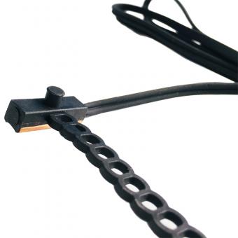
Where the sensor sits matters as much as the number. A PTC bonded into the winding head reads close to the hotspot. One mounted on the frame reads the frame, which can trail the winding by a long time when cooling is blocked. How long depends on the machine, so test it on your design rather than assume it, and choose TNAT for the position the sensor will actually occupy.
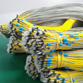
The string is two wires from the motor terminal box to the relay, regardless of how many elements are inside. MZ6 elements can be connected in series as duplex, triple or sextuple kits.
| Item | MZ6 value | Why it matters |
|---|---|---|
| Maximum operating voltage | 30 V DC | Relays measure at about 2.5 V. An insulation tester across the sensor pair is many times this rating. |
| Dielectric strength | AC 2.5 kV | Insulation between the element and the winding it sits in |
| Response time | ≤5 s | A bare-sensor datasheet figure. TDK defines its comparable spec, thermal threshold time, as the time to heat from 25 °C to the rated point by external heating, not as a 63.2 % time constant. Embedded in a varnished winding, the real delay is longer. |
| Maximum controlled temperature | 190 °C | Above this the element is outside its specification |
| Cold resistance, string | ≤300 Ω for three | Relays specify a maximum total cold resistance |
From the Focusens MZ6 series datasheet (MZ6 V2.0).
The voltage limit is the one that gets violated. A typical insulation test on a low-voltage motor uses 500 V DC, more than sixteen times the 30 V DC maximum working voltage in the MZ6 datasheet. WEG tells you to ground all temperature sensors before measuring stator insulation resistance and does not recommend insulation-testing the thermal protectors themselves. Follow the motor maker's procedure, keep the tester off the sensor pair, and check that your own works instruction says so.
The other limit is total cold resistance. Most relay datasheets give a cold-string maximum (750 Ω for the ABB CM-MSS.32, 1500 Ω for the Crouzet ETM, 1.65 kΩ for the ZIEHL MS220KA), and a long sensor cable adds to the string. Where a machine sits far from its panel, confirm that cable resistance plus string resistance stays inside the relay's limit.
The sensor and the relay are covered by different documents, and mixing them up produces specifications that cannot be met.
| Document | Covers |
|---|---|
| DIN VDE V 0898-1-401 (replaced DIN 44081 and DIN 44082 in 2016; current edition 2020-03) | The sensor's resistance limits around TNAT. MZ6 rated points from 90 to 160 °C follow it. |
| IEC 60738-1 | The international generic specification for directly heated PTC thermistors |
| IEC 60947-8 | The relay or control unit that reads Mark A sensors |
| IEC 60034-11 | Built-in thermal protection of the machine as a system |
| IEC 60034-1 | Machine rating, ambient conditions and the thermal class limits TNAT is chosen against |
The wire colour code that identifies each rated temperature is listed in the DIN 44081 and DIN 44082 guide.
Measure the string cold at the panel end, with the sensor pair disconnected from the relay, and confirm it is inside the relay's cold-string limit with the cable included. The DIN limits assume a measuring voltage of 2.5 V or less, so use a multimeter on an ohms range, never an insulation tester. Confirm the works instruction keeps the sensor pair out of insulation testing.
Force a trip with the relay's test button (ABB and Crouzet have one) or by simulating the sensor resistance at the relay terminals as ZIEHL's manual describes, rather than by heating the motor, and confirm the contactor drops and the reset behaves as the application needs, because a self-resetting circuit on a machine that restarts unattended is a hazard rather than a convenience.
Then record which TNAT was fitted. A motor rewound three years later by someone who cannot tell a 130 °C element from a 155 °C one by looking is the reason the colour coding exists.
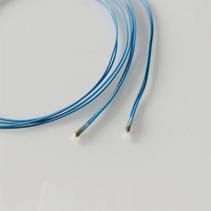
Focusens MZ6 assemblies are built as single, duplex, triple and sextuple kits with rated points from 60 to 190 °C. The 170 °C triple sensor in series is one example; 170 °C is outside the 90-160 °C DIN range, so take its trip margins from its own datasheet. The device families are compared in the PTC thermistor guide, and the full range is under PTC thermistors.
No.1 XiSan Road, Electromechanical Industry Park , High&New Tech.Zone. Hefei,Anhui,China
Tel : +86-551-69109668
Whatsapp : +86-13339100504
Email : info@focusens.com
Skype : melodyliu520






 +86-551-69109668