August 27, 2026
How to Test a Thermocouple with a Multimeter: 5 Steps
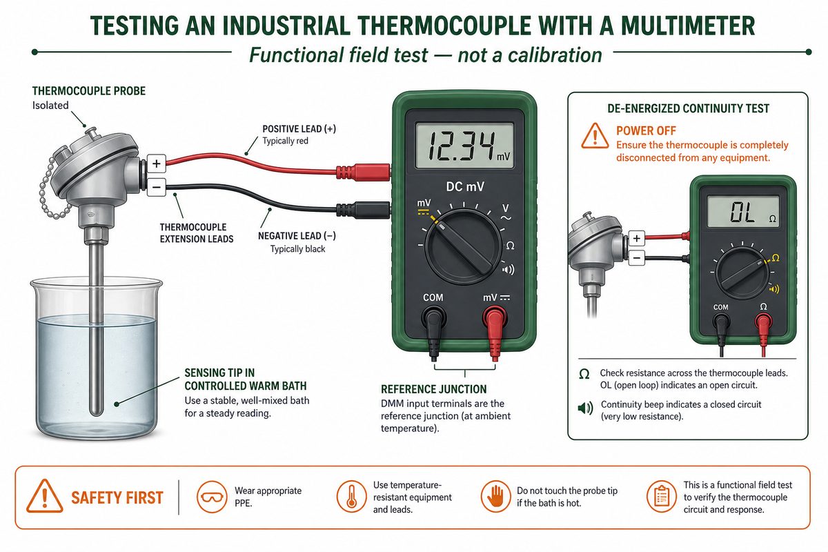
A practical thermocouple test has two parts: check the de-energized circuit for a break, then check whether the sensor produces a smooth, correctly directed DC millivolt change when its measuring junction is heated or cooled. A multimeter can find many field faults, but it cannot by itself prove calibration accuracy. This guide is for industrial J-, K-, T-, E-, N- and S-type thermocouple probes and their wiring. It does not apply a gas-valve thermocouple's appliance-specific millivolt criterion to industrial temperature probes. For an industrial probe, the expected voltage depends on thermocouple type, measuring-junction temperature and reference-junction temperature. Separate the de-energized continuity check from the powered-system and dynamic mV checks. What you need before testing Identify the thermocouple and the receiving instrument before touching the leads. You need a multimeter with DC millivolt and resistance/continuity modes, insulated test leads or the correct thermocouple adapter, a controlled heat or cold source, the thermocouple type/polarity information, and the transmitter or controller manual. Unknown wiring makes a voltage reading ambiguous. Follow the equipment's shutdown, lockout and process-isolation procedure. Never select resistance or continuity mode on an energized circuit. Fluke's multimeter guidance requires circuit power to be disconnected before continuity testing. Record the thermocouple type, wire polarity, terminal numbers, extension-wire type and current instrument configuration before disconnecting anything. Inspect for loose terminals, corrosion, crushed cable, damaged insulation, moisture and an exposed or displaced measuring junction. Determine whether the probe is grounded, ungrounded or exposed if that construction affects your continuity-to-sheath test. Use a controlled bath, dry-block or other source that stays within the probe's approved limits. A lighter or torch is not a universal test source for an industrial probe. If the thermocouple is installed in a hazardous, pressurized or high-temperature process, stop at the approved test point. A multimeter procedure does not replace the plant's safe-work method or the equipment manufacturer's instructions. How to test a thermocouple with a multimeter in five steps The five-step sequence is: identify and isolate the circuit, inspect it, screen it for continuity, establish a raw-mV baseline, then apply a controlled temperature change and isolate the remaining signal path. Keep the test conditions with the reading. A number without thermocouple type and reference-junction temperature cannot be interpreted reliably. Step 1: Identify the type, polarity and test boundary Confirm whether the sensor is J, K, T, E, N, S or another type. Photograph or label the terminals before removal. Decide whether you are testing only the probe, the probe plus extension cable, or the complete sensor-to-transmitter path. Then isolate that boundary according to the equipment manual....
View More







 +86-551-69109668