Categories
Electrode Level Sensor — Working Principle, Wiring & Applications | Focusensing
January 31 , 2024Electrode (conductive) level sensors keep an eye on the level of a liquid by measuring how much electrical conductivity varies between two or more electrodes. They are easy to use, dependable, and often used for conductive liquids in fields like HVAC, food and drink, water and wastewater, and chemical processing. This article tells you how to set it up and wire it, how to fix problems, and how to use it. It also tells you how it works and what it usually outputs.

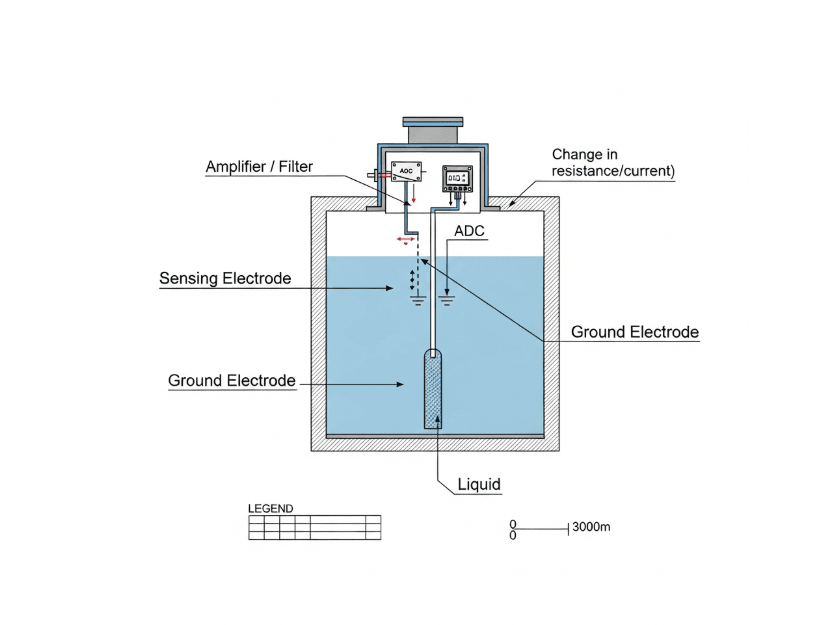
Electrode level sensors use metal probes (electrodes) that are in the liquid. When the liquid connects the electrodes, a small electrical circuit forms. The electronics in the sensor detect changes in current or resistance and turn them into a signal that control systems or PLCs may use (switch output, 4–20 mA, or digital signal).
Probes or electrodes that touch liquid: At the height where the target is, there is a detecting electrode and a reference/ground electrode.
Conductivity path forms: If the liquid is conductive, a tiny current flows between electrodes when the liquid reaches them. Non-conductive liquids (oils) will not bridge the circuit.
Signal detection: The sensor’s conversion circuitry measures the resistance or current change between the electrodes. This can be implemented as voltage sensing, current sensing, or threshold detection.
Signal conditioning: Amplification, filtering, and hysteresis are applied to reduce noise and avoid false triggers from splashes or turbulence.
Output generation: The conditioned signal becomes the sensor output — typically a relay/solid-state switch, open-collector, 0–10 V, or 4–20 mA for continuous monitoring.
Amplification: Raises low-level signals from high-resistance liquids to detectable levels.
Filtering / debounce: Removes transient spikes caused by waves, bubbles, or electrical interference.
AC excitation: Many electrode sensors use AC instead of DC to avoid electrolysis and electrode corrosion.
Reference grounding: Proper grounding prevents floating voltages and reduces false readings.
Calibration / sensitivity adjustment: Allows the sensor to be tuned for different liquid conductivities.
Relay / SPDT — on/off switching for pumps or alarms.
Open-collector / NPN/PNP — compatible with PLC inputs.
Analog (4–20 mA, 0–10 V) — continuous level measurement via a converter module.
Digital (RS485 / Modbus) — for remote monitoring and diagnostics (less common for simple electrode probes).
Mount electrodes at the correct detection heights and secure them to avoid movement.
Use a dedicated ground reference; avoid sharing power-ground paths with heavy machinery.
Keep cable runs away from high-voltage or noisy equipment; use shielded cable when needed.
For multiple-point detection, isolate each electrode channel to prevent cross-talk.
If using AC excitation, verify the excitation frequency to minimize electrochemical effects.
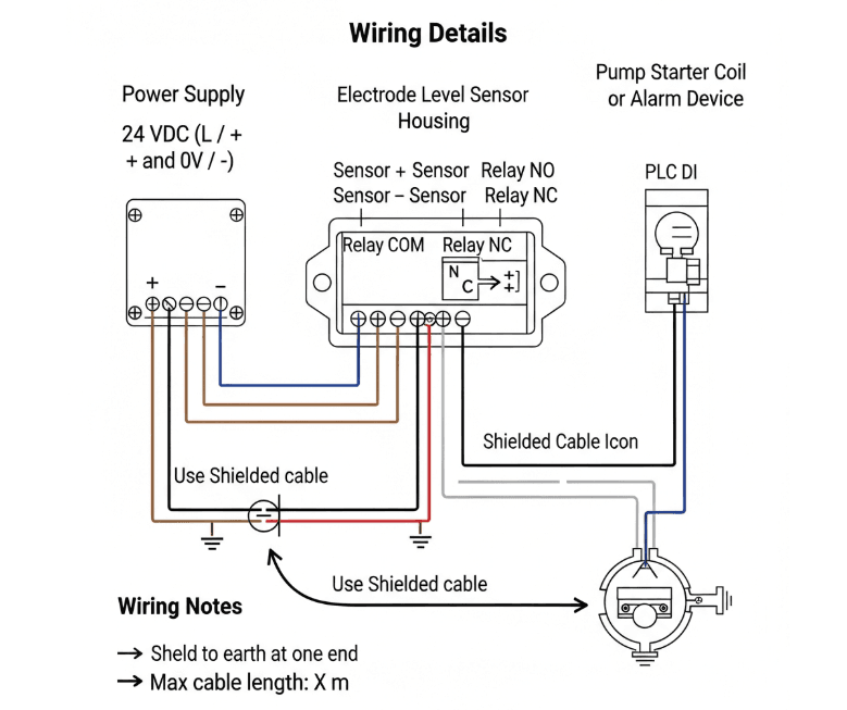
Wiring example (relay output):
L (24 VDC) → Sensor +
Sensor - → 0 V / Ground
Sensor Relay COM → PLC input (or pump starter)
(Include model-specific wiring diagrams in product datasheet.)

False triggering: Check for stray conductive paths (scale, condensation), verify grounding, add filtering or hysteresis.
No detection: Confirm electrode cleanliness, verify wiring and power, check excitation source.
Corrosion / electrode wear: Use corrosion-resistant materials (316 stainless, Hastelloy), or apply sacrificial coatings.
Unsuitable liquid: Electrode sensors require conductive liquids; for oils or deionized water consider capacitive or ultrasonic sensors.
Best for: Conductive liquids — municipal water, brines, wastewater, many chemical solutions.
Not ideal for: Non-conductive liquids (hydrocarbons, pure solvents), highly abrasive slurries without protective sleeves.
Compared to alternatives:
Float switches — simple but mechanical and prone to fouling.
Ultrasonic — non-contact, works on any liquid, but affected by foam.
Capacitive — can handle non-conductive liquids but often requires calibration and is influenced by dielectric changes.
Regularly inspect and clean electrodes to remove scale, biofilm, or deposits.
Use periodic inspection intervals based on process conditions (e.g., monthly for dirty fluids).
Re-calibrate analog converters and verify output signals during scheduled maintenance.
| Parameter | Typical value / note |
|---|---|
| Sensing medium | Conductive liquids (water, brine, many solutions) |
| Outputs | Relay, NPN/PNP, 4–20 mA, 0–10 V |
| Probe material | 316 stainless steel (typical), Hastelloy (optional) |
| Operating temperature | −20 °C to 85 °C (model-dependent) |
| Mounting | Threaded, flanged, or cable-hung probes |